Morgan wrote:
Hi Nick - welcome to the forum!

byoc wrote:
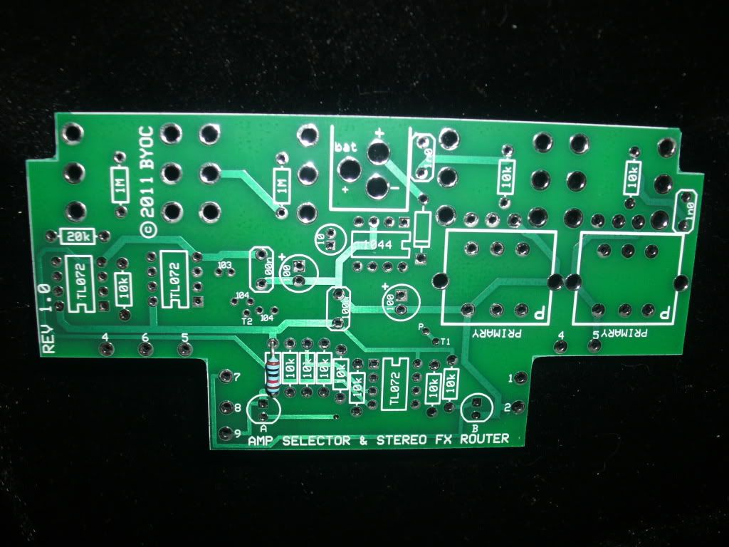
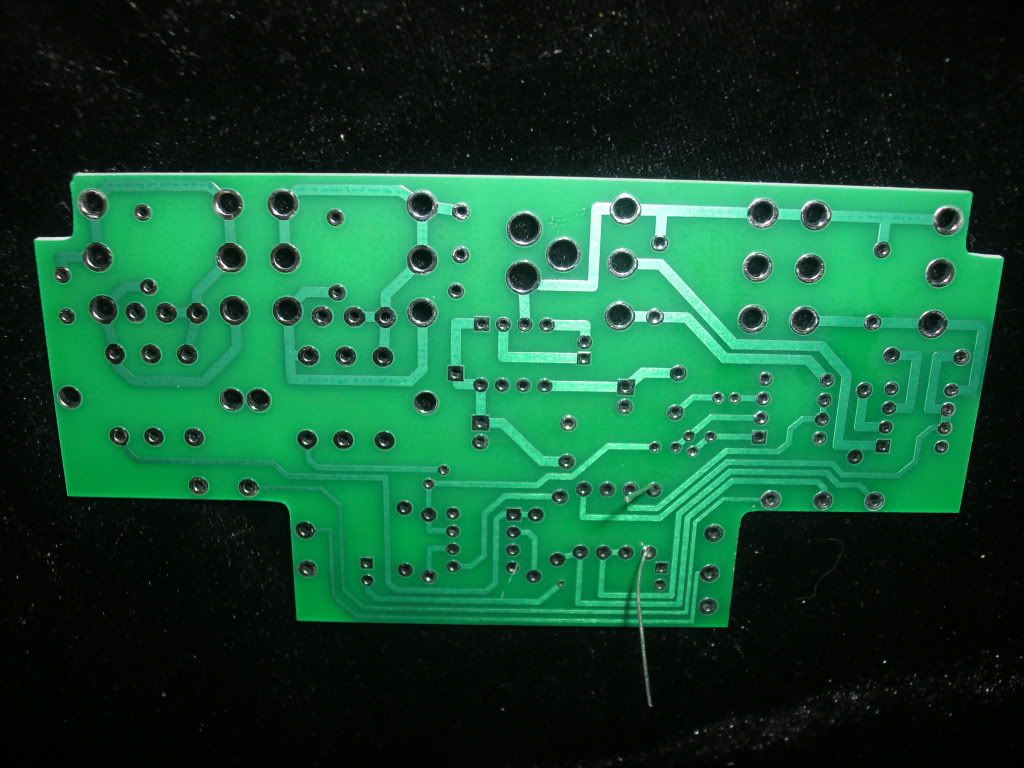
FYI, there's a bonus phase invertion mod built into the PCB. Where is says 103 or 104, you'd stick a 10k or 100k resistor. You'll need a SPDT switch. "P" connects to the Pole. T1 connects to one throw and T2 connects to the other. There's a trace that connects between P an T1 on the top of the PCB. You'd cut that trace.
hello I'm trying to understand the
phase mod. Could you explain the process for the mod in lame terms? I'm a noob, sorry

am I suposed to replace 103 with a 10k resistor or am I supposed to replace 104 with a 100k resistor? or both? what will the difference be? what does "throw" mean? please help.
I've built a digital delay and ping pong and shredder pedal before so I'm not that bad I guess.