Build Your Own Clone Message Board

It is currently Sun Apr 28, 2024 1:26 pm

All times are UTC - 6 hours


Post new topic Reply to topic  [ 8 posts ] 
Author Message
PostPosted: Tue Mar 05, 2024 11:16 am 
Offline

Joined: Tue Mar 05, 2024 10:27 am
Posts: 4
Hello, I have been building the Spring Reverb kit, and have come into some issues with it I was hoping to get some help on. Right now, the main issue is that the LED does not come on, the effect does not work, and bypass is not working either. I've tinkered around plenty with it, and although unsuccessful, I've noted some things that might be helpful:

1. I have just about quadruple checked the wiring and connections for continuity on the board, jacks and footswitch, all appear to be in the correct place. Maybe another set of eyes will show a mistake I made in this area.
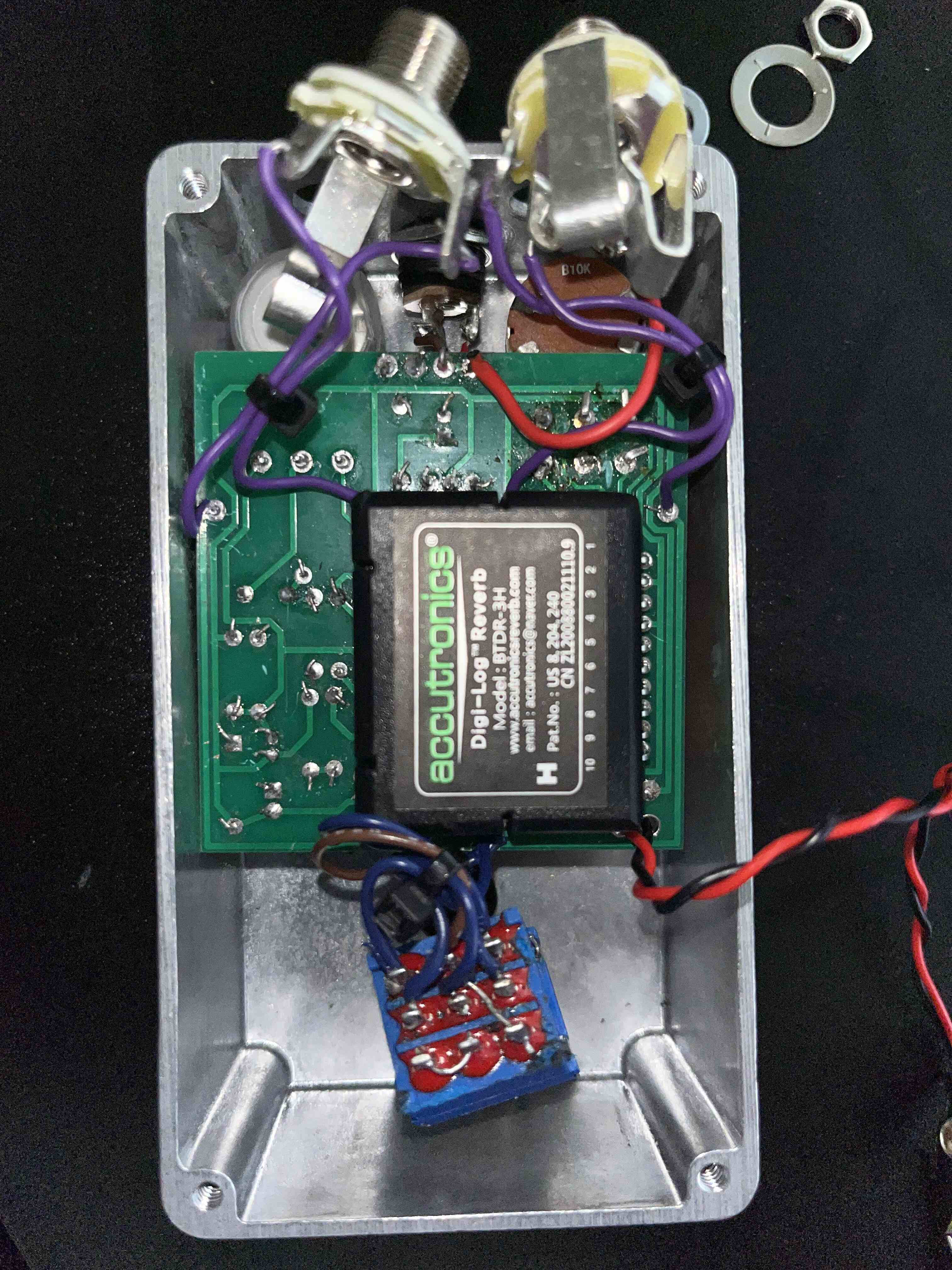
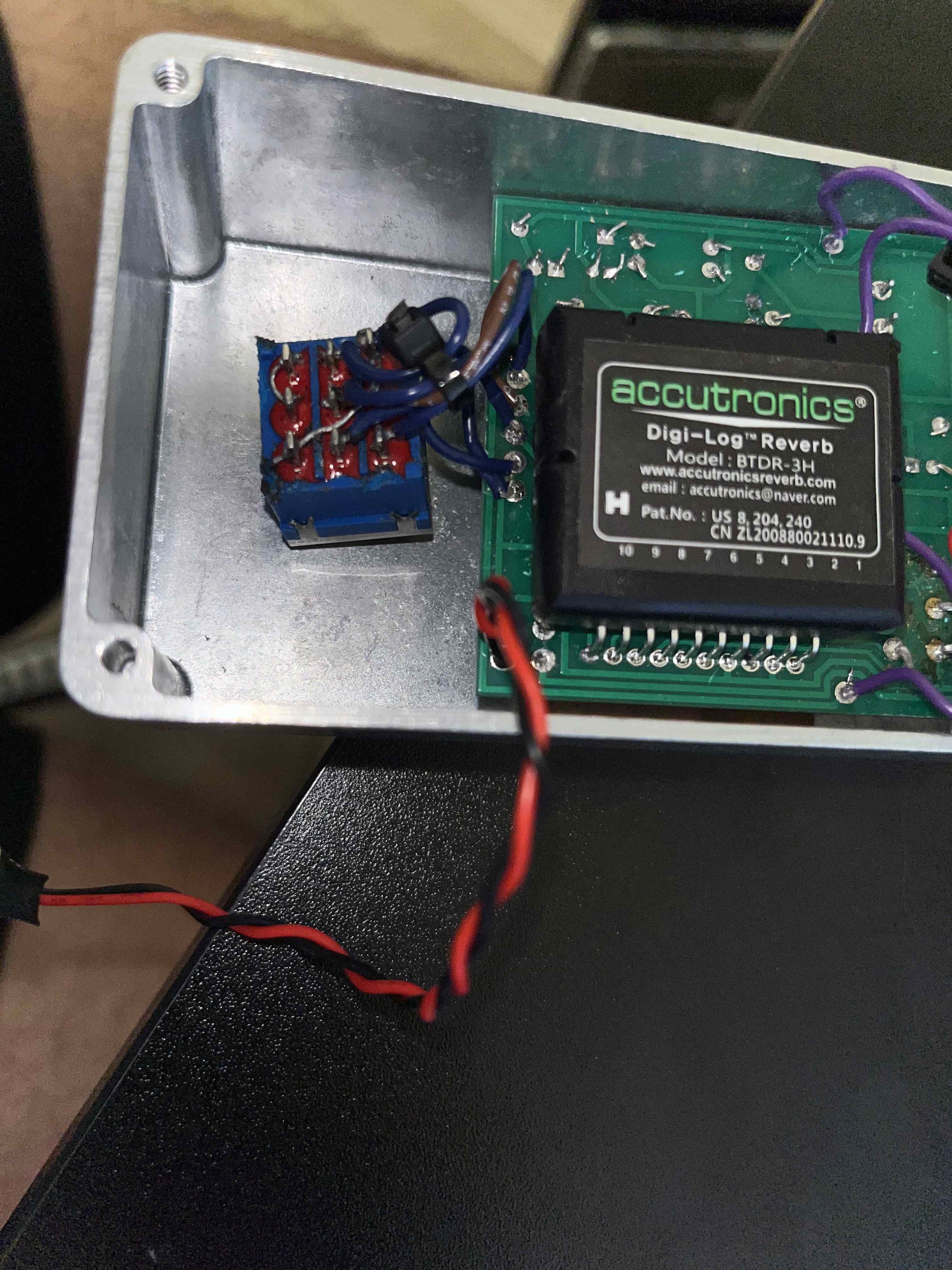
2. On the 9V jack (I am using a center negative power supply), when plugged in, I noticed that the middle (+) pin has 0V when referencing the " - " pin. The other " + " pin does have 9.4V when referencing the " - " pin.
3. When referencing the ground pins for both of the jacks (input/output), there are 8.5V between those ground pins and the " - " pin from the 9V jack.
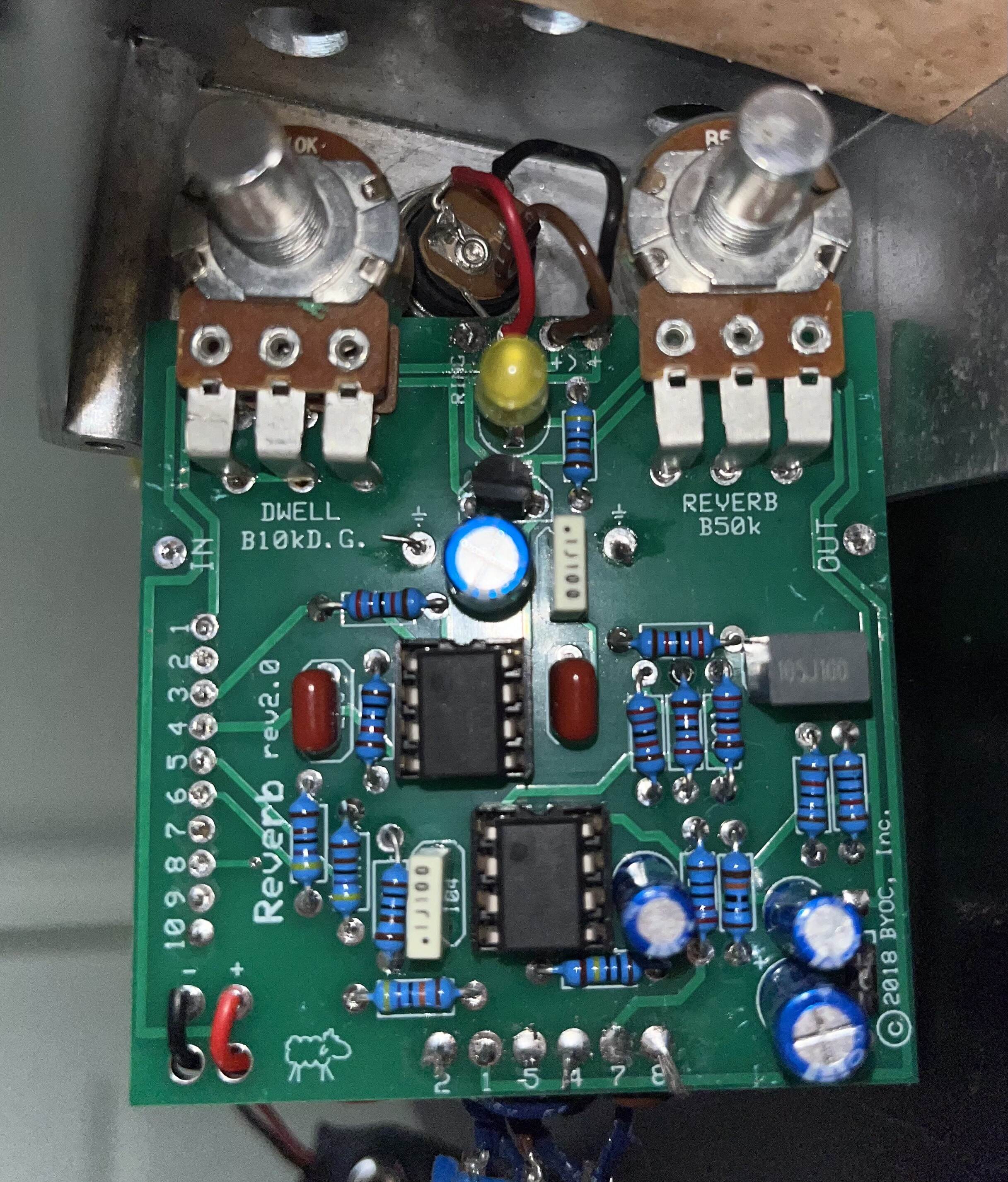
4. I noticed I oriented my pots on the opposing side of the PCB than on the instructions, but I don't think this should make a difference, nor should it keep the pedal from powering on?
5. I noticed the PCB had some cap footprints that were labeled as 104, although the caps I received were labeled 100 (see white caps in image). Again, this shouldn't keep the pedal from powering on is my though
6. When using the 9V " - " pin as reference, most of the pins aside from the grounds referenced in point 3, show about 9V.
7. The AC voltages in the footswitch change when engaging the switch. I can't recall which ones I checked exactly, but they switch between, 0.22 VAC and ~4VAC on toggle.

That's all I could think of at the moment, are there any other voltage/continuity checks that I could to for troubleshooting? I've included images below for reference as well, many thanks for all support in advance!

Attachment:
IMG_0718 (1).jpg
IMG_0718 (1).jpg [ 863.65 KiB | Viewed 1076 times ]

Attachment:
IMG_0720 (1).jpg
IMG_0720 (1).jpg [ 849.79 KiB | Viewed 1076 times ]

Attachment:
IMG_0723 (1).jpg
IMG_0723 (1).jpg [ 869.96 KiB | Viewed 1076 times ]


Top
 Profile  
 
PostPosted: Tue Mar 05, 2024 11:49 am 
Offline
Site Admin
User avatar

Joined: Sun Jan 22, 2006 1:39 pm
Posts: 5991
Location: Richland, WA
Don't use the negative terminal of the DC jack as your reference. Use the sleeve of either jack or a ground point on the PCB. You need to have a guitar cable plugged into the input jack for ground to be completed.

Test for voltage at pin/eyelet 1 of the reverb module.

_________________
*patience is a virtue*

Please do not PM me. email is prefered. keith@buildyourownclone.com


Top
 Profile  
 
PostPosted: Tue Mar 05, 2024 12:24 pm 
Offline

Joined: Tue Mar 05, 2024 10:27 am
Posts: 4
Hi there, thanks for the info Keith. I tested as you suggested, and I got the following results:

1. 9.4V measured between the longest sleeve of the input jack, and pin 1 of the reverb module
2. 0V measured between the short sleeve of the input jack, and pin 1 of the reverb module
2. 0V measured between the sleeve of the output jack, and pin 1 of the reverb module
3. 0V measured between both of the PCB grounds that connect to the jack, and pin 1 of the reverb module


Top
 Profile  
 
PostPosted: Tue Mar 05, 2024 1:33 pm 
Offline
Site Admin
User avatar

Joined: Sun Jan 22, 2006 1:39 pm
Posts: 5991
Location: Richland, WA
georgedelisle wrote:
Hi there, thanks for the info Keith. I tested as you suggested, and I got the following results:

1. 9.4V measured between the longest sleeve of the input jack, and pin 1 of the reverb module
2. 0V measured between the short sleeve of the input jack, and pin 1 of the reverb module
2. 0V measured between the sleeve of the output jack, and pin 1 of the reverb module
3. 0V measured between both of the PCB grounds that connect to the jack, and pin 1 of the reverb module


I'm sorry, but none that helps other than to suggest you simply have a wiring or soldering issue. Ground is ground regardless of where you test from. If you're getting inconsistent results, then that suggests you have broken continuity somewhere. Furthermore, pin 1 of the reverb module is connected to the output of a 5V regulator, so if you are indeed getting 9.4V there, something is wrong. Please don't jump to the assumption that the regulator is bad, and attempt to replace it. Get bypass and your LED working first, and make sure you are taking accurate readings before replacing any components.

Try taking voltage readings at pin 8 of the op amp.

_________________
*patience is a virtue*

Please do not PM me. email is prefered. keith@buildyourownclone.com


Top
 Profile  
 
PostPosted: Tue Mar 05, 2024 2:43 pm 
Offline
Moderator
User avatar

Joined: Tue Jan 02, 2007 1:24 pm
Posts: 16224
Location: Albany, NY
It appears to me that you have the input jack (the stereo one with three solder tabs) mounted on the output side of the enclosure. Are you compensating for that when you insert your input cable? It would be easy to have your I/O cables switched if not. Additionally, with the pots mounted on the component side of the board as you have done, they will operate backwards from the way they normally do, i.e. turning them CW will reduce the dwell time and the reverb intensity.

_________________
“My favorite programming language is SOLDER” - Bob Pease (RIP)

My Website * My Musical Gear * My DIY Pedals: Pg.1 - Pg.2


Top
 Profile  
 
PostPosted: Tue Mar 05, 2024 5:26 pm 
Offline

Joined: Tue Mar 05, 2024 10:27 am
Posts: 4
Hi Keith and duhvoodooman, thanks for the suggestions and catches. My input/output jacks were reversed, and mixed up the wiring on the input jacks, so I decided to reverse the whole thing so now it's all right side up so the pots can work normally. I tested the voltage at pin 1 of the reverb module, and it is now 5V, so that's good news. I also tested pin 8 of both op amps. The top op amp (closest to the 9V jack) was measuring 1.3V, while the bottom op amp is measuring 4.7V at pin 8. However, the LED still doesn't work and neither does the effect, going to check if bypass is at least working now. Thanks!

Best,
G.


Top
 Profile  
 
PostPosted: Wed Mar 06, 2024 10:46 am 
Offline

Joined: Tue Mar 05, 2024 10:27 am
Posts: 4
Hi again, just wanted to update that the bypass and effect are now working, turns out the solutions from Keith and duhvoodooman did the trick, many thanks for that, the reverb sounds beautiful! However, the LED still doesn't turn on, I've tried a few spares I had no luck either. I'm getting 9V on the square pin and 0V on the round one, my thought is that there should be a voltage drop before it hits the LED, is that correct? Many thanks again for helping me get the effect working.

Best,
G.


Top
 Profile  
 
PostPosted: Wed Mar 06, 2024 1:43 pm 
Offline
Site Admin
User avatar

Joined: Sun Jan 22, 2006 1:39 pm
Posts: 5991
Location: Richland, WA
The most common problem with the LED not working is that the builder has the LED in backwards.

If you're certain you have the LED oriented correctly, then use the continuity setting on your multimeter and test to make sure the round solder pad connects to ground when the footswitch is in the "on" state.

_________________
*patience is a virtue*

Please do not PM me. email is prefered. keith@buildyourownclone.com


Top
 Profile  
 
Display posts from previous:  Sort by  
Post new topic Reply to topic  [ 8 posts ] 

All times are UTC - 6 hours


Who is online

Users browsing this forum: No registered users and 3 guests


You cannot post new topics in this forum
You cannot reply to topics in this forum
You cannot edit your posts in this forum
You cannot delete your posts in this forum
You cannot post attachments in this forum

Search for:
Jump to:  
cron
Powered by phpBB® Forum Software © phpBB Group