Build Your Own Clone Message Board

It is currently Sat Apr 27, 2024 10:07 pm

All times are UTC - 6 hours


Post new topic Reply to topic  [ 11 posts ] 
Author Message
PostPosted: Wed Jan 12, 2022 10:41 pm 
Offline

Joined: Fri Jan 07, 2022 4:12 pm
Posts: 9
Greetings, did my second ever BYOC build and am having some issues with it. I believe it's something to do with the grounding.

LED turns on but there's no sound at all when the pedal is on. When bypassed, there's a loud buzzing and faint guitar signal. Pots are not grounding against the board, checked continuity with my multimeter at every place I could think to and couldn't find anything.

Any help would be appreciated, y'all helped me out with my first build and diagnosed the problem really quick. Thanks

Image
Image
Image


Top
 Profile  
 
PostPosted: Thu Jan 13, 2022 11:32 am 
Offline
Moderator
User avatar

Joined: Tue Jan 02, 2007 1:24 pm
Posts: 16224
Location: Albany, NY
I can't see the wire connections on the input jack, but the output jack is definitely wired backwards, so your output signal is going right to ground. Switch the two connections on the jack and see where you're at.

_________________
“My favorite programming language is SOLDER” - Bob Pease (RIP)

My Website * My Musical Gear * My DIY Pedals: Pg.1 - Pg.2


Top
 Profile  
 
PostPosted: Thu Jan 13, 2022 9:28 pm 
Offline

Joined: Fri Jan 07, 2022 4:12 pm
Posts: 9
Hmm... I believe you are correct.

In the instructions, on page 26 the diagram shows wiring as I have it, but the photo of the finished product near the top absolutely has it the other way around. I will reverse and report back


Top
 Profile  
 
PostPosted: Thu Jan 13, 2022 9:38 pm 
Offline
Moderator
User avatar

Joined: Tue Jan 02, 2007 1:24 pm
Posts: 16224
Location: Albany, NY
The diagram on pg. 26 is indeed misleading. I'll let Keith know about that so that it can be corrected.

_________________
“My favorite programming language is SOLDER” - Bob Pease (RIP)

My Website * My Musical Gear * My DIY Pedals: Pg.1 - Pg.2


Top
 Profile  
 
PostPosted: Thu Jan 13, 2022 11:05 pm 
Offline

Joined: Fri Jan 07, 2022 4:12 pm
Posts: 9
Glad I could be of help.

Swapped around the output jack, bypass now works and the buzzing noise is gone. However the effect still does not come on.


Top
 Profile  
 
PostPosted: Fri Jan 14, 2022 11:00 am 
Offline
Moderator
User avatar

Joined: Tue Jan 02, 2007 1:24 pm
Posts: 16224
Location: Albany, NY
OK, gotta win the war one battle at a time! :mrgreen:

Do you know how to measure DC voltage with your multimeter? If so, please get voltage readings on all the pins of each of the three IC's and report your results here. See left side of the image below for the numbering of the pins.

Image

_________________
“My favorite programming language is SOLDER” - Bob Pease (RIP)

My Website * My Musical Gear * My DIY Pedals: Pg.1 - Pg.2


Top
 Profile  
 
PostPosted: Fri Jan 14, 2022 12:58 pm 
Offline

Joined: Fri Jan 07, 2022 4:12 pm
Posts: 9
The 4558 reads:
1- 5.42
2. 5.41
3. 2.72
4- 0
5- 5.20
6. 5.51
7. 5.22
8. 7.64

The TL072 near the filter pot:
1- 5.33
2- 5.24
3- 5.19
4- 0
5- 0.1
6- 7.06
7- 7.05
8- 7.63

The TL072 near the level pot:
1- 5.23
2- 5.22
3- 5.17
4- 0
5- 5.82
6- 7.01
7- 6.95
8- 7.62


Top
 Profile  
 
PostPosted: Fri Jan 14, 2022 2:08 pm 
Offline
Moderator
User avatar

Joined: Tue Jan 02, 2007 1:24 pm
Posts: 16224
Location: Albany, NY
Not quite sure what to make out of those results. Pin 4 on all three op amps connects to ground, so should read 0, which they do. Pin 8 is your incoming power source, which should be at 9V or a bit higher; if you're running off a battery, it should be replaced with a fresh one.

Generally, the remaining 6 pins on all three IC's should be right about 1/2 of your power source voltage, so about 3.8V plus or minus a couple of tenths, based upon your pin 8 readings. But you're reporting significantly higher values than that on most of them, along with a couple of low ones. I'd love to check & confirm the pin voltages myself, but I don't own an El Distorto Segundo. Maybe another of our forum moderatos could check this.

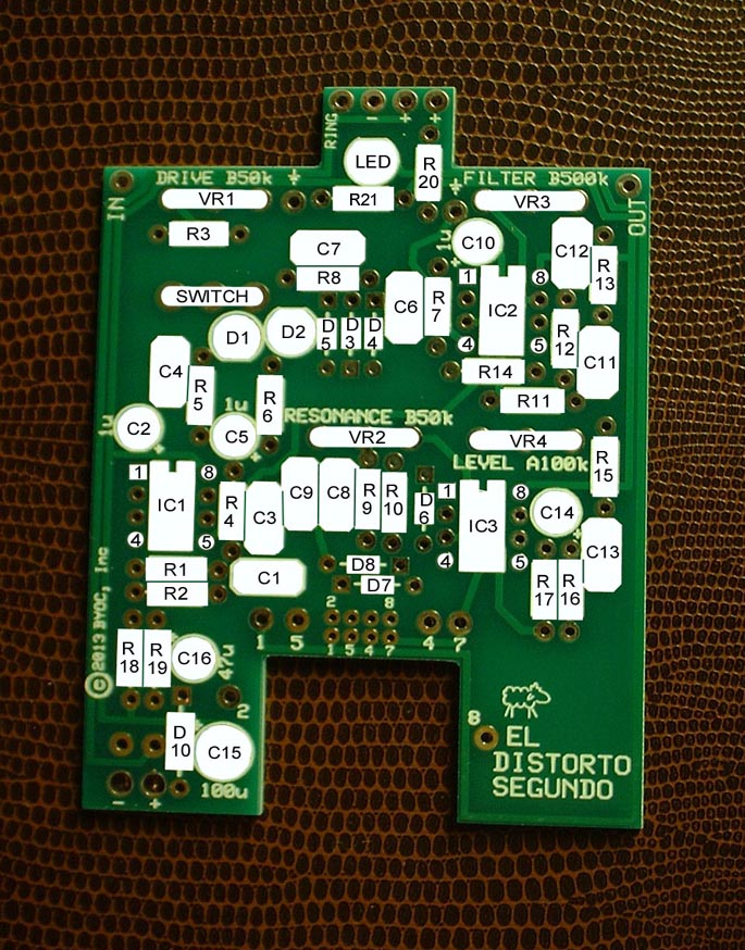
I would start by checking the voltage at the R18/R19 voltage divider (see labeled PCB map below) that provides the 1/2V for the circuit. Measure that at the top lead of either one of those two 33K resistors and report your result here.

You might also want to work through THIS PROCESS, since it solves an amazing number of pedal performance problems.

Image

_________________
“My favorite programming language is SOLDER” - Bob Pease (RIP)

My Website * My Musical Gear * My DIY Pedals: Pg.1 - Pg.2


Top
 Profile  
 
PostPosted: Fri Jan 14, 2022 5:47 pm 
Offline

Joined: Fri Jan 07, 2022 4:12 pm
Posts: 9
Got it working. First thing, you are right my 9v battery was dying so the voltage reading wasn't great. Got that taken care of first.

Next I decided to check pin five of that one opamp that was reading 0.1 and the Solder was slightly over the pad and just barely touching the one next to it. Once I fixed that, voltage readings were better, and now the pedal works perfectly

Thanks again!


Top
 Profile  
 
PostPosted: Fri Jan 14, 2022 7:52 pm 
Offline
Moderator
User avatar

Joined: Tue Jan 02, 2007 1:24 pm
Posts: 16224
Location: Albany, NY
Ah, great news! Enjoy the pedal!

_________________
“My favorite programming language is SOLDER” - Bob Pease (RIP)

My Website * My Musical Gear * My DIY Pedals: Pg.1 - Pg.2


Top
 Profile  
 
PostPosted: Sat Jan 15, 2022 10:46 am 
Offline
Moderator
User avatar

Joined: Tue Jan 02, 2007 1:24 pm
Posts: 16224
Location: Albany, NY
BTW, if you're going to power the pedal with a battery, pull the cable out of the input jack when you're done playing. This will preserve the battery, since it grounds through the sleeve of the input cable; no ground connection to complete the circuit = no drain on the battery.

Contrary to what many players think, switching to bypass mode on the footswitch does NOT turn off the power to the effect circuit! The pedal will remain energized as long as a ower source is connected and there's a cable in the input jack to provide the needed ground path.

_________________
“My favorite programming language is SOLDER” - Bob Pease (RIP)

My Website * My Musical Gear * My DIY Pedals: Pg.1 - Pg.2


Top
 Profile  
 
Display posts from previous:  Sort by  
Post new topic Reply to topic  [ 11 posts ] 

All times are UTC - 6 hours


Who is online

Users browsing this forum: No registered users and 5 guests


You cannot post new topics in this forum
You cannot reply to topics in this forum
You cannot edit your posts in this forum
You cannot delete your posts in this forum
You cannot post attachments in this forum

Search for:
Jump to:  
Powered by phpBB® Forum Software © phpBB Group