duhvoodooman wrote:
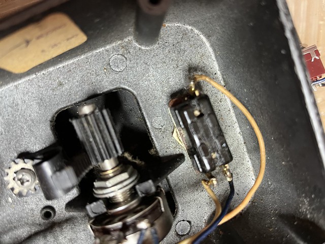
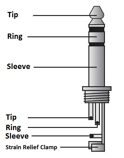
John, I can't be certain from the photos: does the input jack have two lugs (mono) or three (stereo/"TRS")? Looks like the latter.
Bob it has 3 on the input as a stereo. I've gone back and forth on ground vs sleeve on this jack. I can talk myself out of either one. I've spent a lot of time trying to work this out before I start. I think I may have it worked out but who knows. I've been locating vids and found some with the exact PCB and are much cleaner than this one.
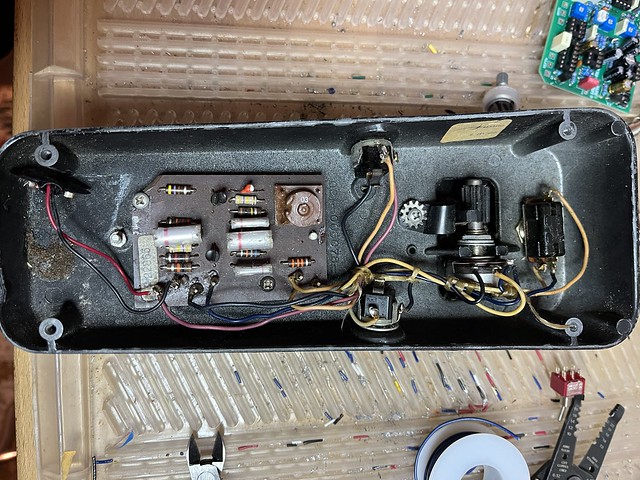
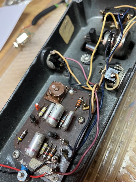
I've taken many pics and wrote down what goes to what in case I have to just pull what I do and put it back in how it was.
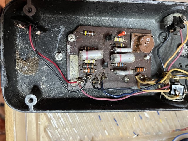
What I think I have on the PCB for the 6 terminals as it is now is:
1- Goes to Lug 2 of the pot.
2- PCB in
3- PCB out
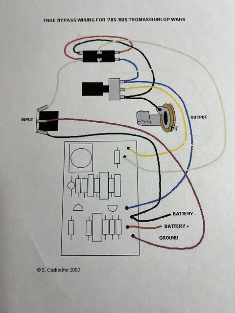
4- Ring going to battery neg ( I hope as this is where my mind tells me the black wire goes to ground/sleeve )
5- 9v+
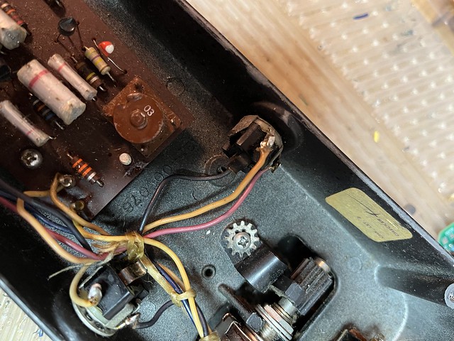
6- Ground for both battery and input jack ( again this is where I'm thinking well it looks like this goes to the sleeve but the drawing on the attached pic says ground. )
I think part of my issue is these old jacks and what I think I see on the input jack vs what really is. Above is what I think I see on the input jack. The wire that you can't really see good is the black wire that runs from terminal 4 and goes under the input jack. I'm torn as black is what I think of in terms of "major" ground but I would swear it is the sleeve here. The red/faded pink runs form terminal 6 to what I hope is the ground and I intend to treat it as such as I rewire. I also think this as I've stared at the jack terminals and determined this to the best of my ability.
The switch that I'm putting in I'm trying to correlate with the existing wiring of course.
If it was my old wah and not his I would have already wired up and if it didn't work cross that off and move a few wires until I figured it out. I'm probably overthinking it worrying about messing up his vintage wah when it's really only wires and it's not like I'm pulling parts on the PCB and replacing them. But if I didn't worry like this I wouldn't be me

_________________
powerpopguy wrote:
warm places theory sounds plausible. Occasionally, I wake up and think my snake is missing too, but it turns out it's just a chilly morning.


